Cessna 152 Systems and Serial-Dependent Changes
Cessna 152 systems combine recognizable family architecture with specific electrical, control and equipment relationships. The U.S. 152 installation includes a 24-volt battery and 28-volt DC system, electric flaps and a stock gravity-fed carbureted fuel arrangement. Those descriptions are useful orientation, but exact components, optional equipment and production changes still depend on model, serial and current configuration.


For focused questions across the two families, use the systems topic guide. This Cessna 152 reference retains the detailed family records and their applicability.
Use the cross-family flap reference to distinguish shared electric actuation from different travel limits and separate component issues. A production description does not establish the present installed system.
The model guide establishes the four identities, while the serial reference preserves exceptions and year conflicts. This page describes architecture and source effectivity. It does not establish which replacement parts or modifications are installed, provide maintenance procedures or certify a particular system's condition.
Flight Controls and Trim
The source describes control-wheel and pedal inputs transmitted through cables, pulleys, bellcranks and related structures to the control surfaces. Elevator trim uses a manual control and trim-tab arrangement. These descriptions identify the broad control paths; they do not establish identical brackets, hinges, travel limits or rigging instructions for every serial.
Aileron changes occur at several different effectivity boundaries. A droop-rigging entry, crossover-turnbuckle relocation, control-Y/bellcrank detail and later hinge change should remain separate research topics. The word aileron is too broad to establish that two source rows describe the same assembly or change.
The specifications page preserves the model-year serial-break descriptions, while the transition table below retains the systems-source wording. In particular, the crossover-turnbuckle entry uses an A152 boundary different from the control-Y/bellcrank entry. Do not resolve that by guessing a typo or merging the events; investigate the exact assembly and controlling manual figure.
Flight controls
| Subsystem | Factory Applicability | Architecture / Components | Operational Interface | Configuration Status | Primary Source |
|---|---|---|---|---|---|
| Aileron | All | Control wheel/Y, cables, pulleys, bellcranks, push-pull rods, hinges and balance weights. | Roll control. | Standard; exact hinge/bellcrank detail changes by serial. | [1] |
| Elevator | All | Control column, cables/pulleys, elevator torque/control structure, hinges. | Pitch control. | Standard. | [1] |
| Rudder | All | Pedals, cables/pulleys, rudder; pedals also interface with nosewheel steering. | Yaw control and ground steering input. | Standard. | [1] |
| Elevator trim | All | Manual trim wheel/control, cables, actuator and elevator trim tab. | Pitch trim. | Standard; rigging data by model. | [1] |
Electric Flaps and Their Maintenance Context
The stock electric-flap description includes a motor/transmission, cables or linkage, cockpit switch and limit or operating switches with indication appropriate to the era. The existence of electric operation does not prove that every actuator, circuit or indication detail is identical. Exact component effectivity remains part of maintenance and parts research.
The AD guide separates the flap-actuator travel-stop topic from the wing-flap cable-clamp topic. Those concerns have their own serial and configuration conditions. A broad statement that the flaps were checked is not evidence that every applicable instruction has been addressed.
The known-issues reference explains the failure-mode and prebuy context. A recorded concern is not a finding of a defective actuator on every aircraft. The aircraft records, installed assembly and applicable inspection evidence determine what remains relevant to an individual installation.
Wing flaps
| Subsystem | Factory Applicability | Architecture / Components | Operational Interface | Configuration Status | Primary Source |
|---|---|---|---|---|---|
| Electric flaps | 150F and later; 152/A152; applicable Reims | Motor/transmission, cables/linkage, cockpit switch, limit/operating switches and indication by era. | Electrically selected flap extension/retraction. | Standard in applicable models; circuitry changes by serial. | [1] |
Electrical Generation, Starting and Ignition
The U.S. 152 alternator row explicitly describes a 24-volt battery, 28-volt DC system and 60-amp alternator. Battery voltage and nominal system voltage are related but different labels. A generic reference to the preceding family's electrical arrangement should not replace this documented 152 installation context.
Starting and ignition also need to remain distinct. The starter uses the aircraft electrical system, while the stock dual-magneto description identifies ignition independent of the main aircraft bus. That architectural distinction is not proof of the exact magnetos, switch or accessories currently installed. The engine reference and production-change records provide narrower equipment context.
Optional external power, lighting and equipment-dependent electrical or instrument arrangements retain their qualifications. A factory option is not evidence of installation. For an actual wiring or appliance question, use the aircraft equipment identification and serialized documentation rather than selecting a circuit description solely because it appears on the family page.
Electrical
| Subsystem | Factory Applicability | Architecture / Components | Operational Interface | Configuration Status | Primary Source |
|---|---|---|---|---|---|
| Starter circuit | Stock family | Battery/bus, ignition/start control, starter contactor/solenoid and starter. | Engine cranking. | 12/24 V installation varies. | [1] |
| 152 alternator architecture | 152/A152 | 24 V battery / 28 V DC system with 60 A alternator. | Electrical generation. | Standard stock architecture. | [2] |
| Master switch | Later family | Battery and alternator control; later split BAT/ALT arrangement. | Connects battery/bus and alternator field. | Era/configuration dependent. | [3] |
| Overvoltage protection | Later alternator family | Sensor/protection removes alternator field/output when overvoltage occurs; warning indication by configuration. | Charging-system protection. | Exact reset/warning logic by POH/wiring. | [3] |
| Circuit protection | All | Fuses and/or circuit breakers, bus distribution and wiring. | Protects circuits. | Ratings and implementation are serial/equipment specific. | [1] |
| External power | Optional applicable aircraft | External DC receptacle/contactor arrangement where installed. | Ground starting/power. | Optional, voltage must match aircraft. | [3] |
| Lighting | All, equipment varies | Navigation/position, landing/taxi, beacon/strobe and cabin/panel lighting as equipped. | Visibility/illumination. | Optional/equipment-list dependent. | [4] |
Electrical / engine interface
| Subsystem | Factory Applicability | Architecture / Components | Operational Interface | Configuration Status | Primary Source |
|---|---|---|---|---|---|
| Ignition switch / magnetos | Stock family | Dual magnetos independent of main aircraft bus; ignition switch grounds/ungrounds magnetos. | Ignition and engine shutdown. | Exact magneto model and installation require engine and aircraft records. | [1] |


Electrical / instruments
| Subsystem | Factory Applicability | Architecture / Components | Operational Interface | Configuration Status | Primary Source |
|---|---|---|---|---|---|
| Pitot heat | Optional applicable | Electrical pitot heating element and protected circuit. | Anti-ice for pitot head. | Optional. | [1] |
Fuel Delivery and Engine Controls
The stock fuel architecture connects two wing tanks, venting, lines, a shutoff valve, strainer, carburetor feed and primer. This explains why fuel-system research involves more than nominal capacity. Adequate tank quantity does not establish the condition or correct installation of every component along the delivery path.
Throttle and mixture descriptions identify mechanical controls whose rigging depends on the actual engine and aircraft installation. The primer is a separate starting-enrichment component in the source. This reference describes their roles without replacing operating procedures or adjustment instructions.
The fuel guide distinguishes standard and long-range tanks, indication and loading quantities. A capacity option can coexist with different component effectivity and maintenance history. An installed alteration requires its own approval and document context rather than automatic use of the original stock-system description.
Fuel
| Subsystem | Factory Applicability | Architecture / Components | Operational Interface | Configuration Status | Primary Source |
|---|---|---|---|---|---|
| Gravity fuel supply | Stock carbureted family | Two wing tanks, venting, lines, shutoff valve, strainer, carburetor feed and primer. | Fuel supply to carburetor. | Tank capacity/options vary. | [1] |
| Quantity indication | Later family | Tank float transmitters and panel indicators. | Fuel quantity indication. | Electrical; exact sender/gauge by year. | [1] |
| Drains | All stock family | Tank sump drains plus strainer/drain provisions. | Contamination/water sampling. | Locations vary by tank/system era. | [1] |
Engine installation
| Subsystem | Factory Applicability | Architecture / Components | Operational Interface | Configuration Status | Primary Source |
|---|---|---|---|---|---|
| Induction / carb heat | Stock O-200/O-235 installations | Filtered induction plus heated alternate air from exhaust heat-exchanger/shroud. | Carburetor air and ice mitigation. | Powerplant-specific details vary. | [1] |
| Throttle | All stock | Mechanical push-pull control with friction arrangement. | Engine power command. | Rigging by exact engine/aircraft. | [1] |
| Mixture | All stock | Mechanical mixture control to carburetor. | Mixture command / idle cutoff. | Rigging by exact engine/aircraft. | [1] |
| Primer | Stock family | Manual primer supplies fuel to intake for starting. | Cold-start enrichment. | Must lock after use. | [1] |
Landing Gear and Brakes
The landplane architecture includes main gear, a steerable nose gear/shock strut and a shimmy dampener. These entries describe function and broad components; brake assembly, vendor and procedural details can vary. A familiar tricycle layout does not establish exact part interchangeability across model years.
The systems transition source identifies revised brake-master-cylinder configuration or procedure beginning with 1979 models. That is a reason to retain model-year and serial evidence during maintenance research. A procedure appropriate to an earlier assembly should not be assumed correct for a later one because both belong to Model 152.
The source's landplane qualifications remain attached. The 150 family's approved float-related rows are not presented as generic 152 equipment. Similarly, current gear and brake condition must be established on the aircraft, independently of factory architecture or an eligible production group.
Landing gear
| Subsystem | Factory Applicability | Architecture / Components | Operational Interface | Configuration Status | Primary Source |
|---|---|---|---|---|---|
| Fixed landing gear | Landplanes | Spring-steel main gear plus steerable nose gear/shock strut. | Ground support, steering, braking. | Standard landplane. | [1] |
| Shimmy dampener | Landplanes | Hydraulic shimmy dampener on nose steering system. | Damps nosewheel oscillation. | Standard/configuration by manual. | [2] |
Brakes
| Subsystem | Factory Applicability | Architecture / Components | Operational Interface | Configuration Status | Primary Source |
|---|---|---|---|---|---|
| Hydraulic wheel brakes | Later family | Pedal master cylinders, hydraulic lines, single-disc wheel brakes; copilot pedals interconnected where installed. | Differential braking and stopping. | Brake assembly/vendor details vary. | [1] |
| Parking brake | Applicable landplanes | Cockpit control mechanically retains brake-system pressure. | Parking. | Standard on cited later family. | [1] |
- [1] 152 POH
Instruments, Warning and Cabin Equipment
Pitot and static descriptions identify the pressure sources and instruments they serve. Pitot heat and other equipment-dependent features remain optional or installation-specific where the source says so. A panel photograph or family model name does not establish the complete installed instrument configuration or its maintenance state.
The later-family pneumatic stall-warning description uses a leading-edge inlet, tubing and air-operated horn. This is an architectural statement, not proof that the warning system is functioning correctly. The applicable aircraft procedures and inspection evidence are needed for a serviceability question.
Cabin heat is associated with an exhaust heat-exchanger/shroud and ducting arrangement. That connection explains why exhaust integrity and cabin-heat research are related. It does not turn every exhaust concern into a confirmed cabin problem. The exhaust issue context retains the specific affected scope and evidence requirements.
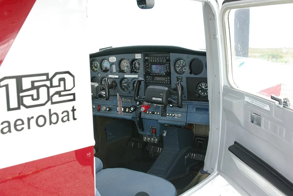

Instruments
| Subsystem | Factory Applicability | Architecture / Components | Operational Interface | Configuration Status | Primary Source |
|---|---|---|---|---|---|
| Pitot system | All | Pitot head/tube, pressure line, ASI. | Dynamic pressure. | Pitot heat optional where installed. | [1] |
| Static system | All | Static source/plumbing to ASI, altimeter, VSI and other instruments as installed. | Static pressure reference. | Port arrangement varies by era. | [1] |
| Engine indications | All | Tachometer, oil pressure, oil temperature and fuel indication plus equipment-dependent instruments. | Engine/system monitoring. | Sensor architecture varies. | [2] |
| Flight instruments | All | ASI, altimeter, compass and other installed flight instruments; VSI/gyro/turn instruments by equipment. | Flight reference. | Power source varies. | [3] |
Utility
| Subsystem | Factory Applicability | Architecture / Components | Operational Interface | Configuration Status | Primary Source |
|---|---|---|---|---|---|
| Pneumatic stall warning | 150F and later; 152/A152 | Leading-edge inlet, tubing and air-operated horn. | Stall warning. | Standard cited later architecture. | [1] |
| Cabin heat | All | Exhaust heat exchanger/shroud, valve/control and cabin ducting. | Cabin heating / defrost source. | Exhaust integrity critical. | [2] |
| Cabin ventilation | All | Fresh-air inlets/ducts/outlets and controls. | Ventilation. | Cabin-era dependent. | [2] |
| Defrost | Later family | Cabin heat/air routed to windshield outlets. | Windshield defog/defrost. | Ducting varies. | [1] |
Utility / instruments
| Subsystem | Factory Applicability | Architecture / Components | Operational Interface | Configuration Status | Primary Source |
|---|---|---|---|---|---|
| Vacuum system | When equipped | Dry engine-driven pump, relief valve, filter, suction gauge, gyro plumbing. | Powers vacuum gyros. | Equipment-dependent. | [1] |
Cabin
| Subsystem | Factory Applicability | Architecture / Components | Operational Interface | Configuration Status | Primary Source |
|---|---|---|---|---|---|
| Doors/latches | All | Hinges, latch/handle, seals; Aerobat quick-release provisions where applicable. | Cabin access/security. | Aerobat differs. | [1] |
| Seats/tracks/locks | All | Adjustable seats, tracks, rollers/locks/stops. | Occupant positioning. | Configuration and service changes vary. | [1] |
| Belts/harnesses | All | Lap belts and shoulder harnesses as equipped; Aerobat enhanced restraint installation. | Occupant restraint. | Year/equipment/retrofit dependent. | [1] |
Production Transitions and Exact Effectivity
The transition table records electrical-generation context, aileron rigging, brake detail, control-Y/bellcrank changes and later aileron hinges. The before/after wording is retained with the source's effectivity. A production transition narrows a factory relationship; it does not prove that a surviving aircraft has never received replacement or altered equipment.
Mixed U.S./Reims effectivity strings must keep all prefixes and serials. A French threshold cannot be replaced by its visually similar U.S. counterpart. Some broader rows explicitly name U.S. 152/A152 only, while others include Reims or describe family-wide architecture. The model-detail references do not inherit every broad system row as an exact installation claim.
The model-year specification records also describe a cabin-door latch change and a later ventilation change within the 1981 context. Those are separate cabin systems, with different standard and Aerobat serial triggers. An aircraft can therefore fall after one change and before the other while retaining the same model and year label. Keep that distinction when choosing a parts illustration or investigating an advertised interior feature; the year alone does not resolve both installed assemblies.
| Effectivity | System | Before | After / Change | Source |
|---|---|---|---|---|
| 150 family -> 152/A152 | Electrical | 14 V DC | 28 V DC; TCDS exact serial effectivity | [1] |
| 15279473/A1520736/F15201428/FA1520336 -> next serials | Aileron rigging | 20 up / 14 down | 20 up / 15 down plus 1.5 deg droop | [2] |
| 152 through 1978 -> beginning 1979 models | Brake master cylinder | Earlier master-cylinder detail | Revised master-cylinder configuration/procedure in service manual | [2] |
| Through 15281426/A1520785/F1521538/FA1520352 -> next serials | Aileron control Y/bellcrank detail | Earlier configuration | Later configuration shown in service manual figure | [2] |
| Through 15285915/A1521027 -> later serials | Aileron hinge | Earlier hinge/pin style | Later hinge style; service information addresses hinge improvement | [3] |
From System Description to Maintenance Evidence
A useful maintenance question identifies the affected function, the installed assembly and the controlling document. For example, an aileron concern should be narrowed to rigging, hinge, cable or control structure before selecting the relevant effectivity. Merely collecting every aileron-related row can obscure the distinction rather than resolve it.
The manuals reference separates maintenance manuals, parts catalogs, service information and aircraft operating documents. A parts illustration can help identify an assembly without establishing the complete inspection or adjustment requirement. A handbook can describe operation without supplying a maintenance procedure.
For owners and buyers, preserve the difference between what the source says about original architecture and what the aircraft records or inspection establish today. A later component replacement, approved modification or incomplete maintenance history can change the research path. The Cessna 152 pillar connects these subjects while leaving unresolved configuration and condition visible.
Individual Cessna 152 Model References
- Cessna 152 - 1978-1985
- Cessna A152 Aerobat - 1978-1985
- Reims/Cessna F152 - 1978-1986
- Reims/Cessna FA152 Aerobat - 1978-1986
Related Cessna 152 Subjects
- Cessna 152 aircraft reference
- Serial ranges and identity exceptions
- Models and Variants
- Specifications and Certified Limits
- Engines and Applicability
- Propellers and Approved Applications
- Performance by Model Year
- Fuel Capacity and Tanks
- Weight, CG and Loading
- Airworthiness Directives
- Known Issues and Prebuy Research
- Manuals and Documents