Cessna 150 and 152 Design and Construction
The Cessna 150 and 152 combine a metal airframe, a wing above the cabin, an engine in the nose and a conventional tail. In their familiar landplane configuration, two main wheels and a nose wheel remain extended throughout flight. Understanding this arrangement means following connections: the wing joins the cabin structure, the cabin carries controls and occupants, and the fuselage links the engine, landing gear and tail. Each system occupies part of that physical structure.
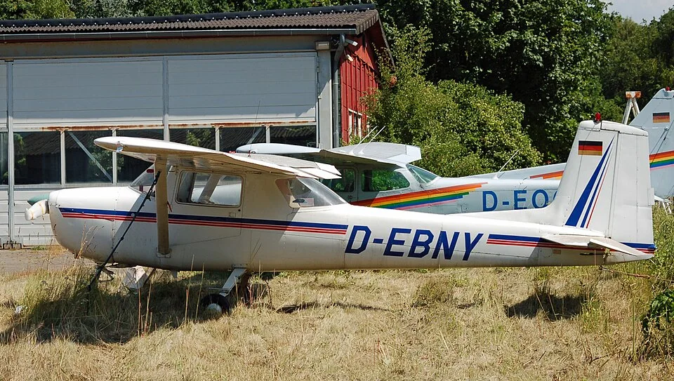

This article explains those relationships across the family, using the later 150M and standard 152 as descriptive examples where construction detail is needed. Earlier generations, Reims aircraft, Aerobats and approved alterations require their own model context. The Cessna 150 and Cessna 152 articles introduce the aircraft as a whole; here the emphasis is on how their parts fit together.
Reading the aircraft from nose to tail
The engine and propeller form the forward power installation. Behind them, the cabin sits beneath the wing, with the baggage space aft of the two main seats. The rear fuselage narrows toward the empennage, the name for the complete tail assembly. A wing strut on each side connects the wing to the lower fuselage. Those external braces are structural members, distinct from the landing-gear legs below the aircraft.
- Engine installation and forward propeller
- High wing; an external strut braces it to the lower fuselage
- Cabin beneath the wing
- Baggage space behind the main seats
- Rear fuselage leading to the empennage
- Nose gear
- Main gear; only the near wheel is represented
- Vertical stabilizer, the fixed fin
- Rudder, behind the fin
- Horizontal stabilizer and its trailing-edge elevator
The high-wing arrangement places the wing structure and its attachments above the occupants. It also places the wing fuel tanks above the engine's fuel-metering installation, part of the geometry of the stock gravity-fed fuel system. Neither relationship makes the structure or fuel system self-explanatory: attachments carry loads, and fuel still passes through lines and components. The cabin article follows the same aircraft from the occupants' viewpoint, including the windows, doors and controls that interrupt a simple external silhouette.
The fuselage is a working structure
An airframe is the aircraft's structural body, rather than its engine or removable equipment. In the 150M construction description, the fuselage uses semi-monocoque construction: metal skin works with internal frames, bulkheads and lengthwise stiffeners. The skin is therefore more than a weather cover. The framework maintains the body's shape and provides attachment structure while the skin participates in carrying loads. The 150M handbook reference describes that construction in its airframe section.
The cabin is part of this structure. Wing attachments, door posts, gear attachments and the forward engine-support structure meet around the occupied part of the fuselage. A door opening is consequently an opening in a structural assembly, rather than evidence that the surrounding metal is merely interior trim. Farther aft, the fuselage connects the tail to the rest of the aircraft. The visible shape and the hidden attachment details answer different questions about the same body.
This is why an aircraft's repair history matters alongside its model identity. A repaired skin panel, a replacement fitting and a cosmetic interior refurbishment describe different kinds of work. The structural prebuy guide and damage-history article connect these distinctions with inspection and records. A general description of semi-monocoque construction cannot establish the acceptability of a particular repair or the condition of an attachment.
Wing, struts and trailing-edge surfaces
The later handbook description identifies a metal wing built around spars and ribs beneath aluminum skin. Spars run along the span; ribs help establish the wing section. The external strut braces the wing to the fuselage. These names describe different structural jobs, so a reference to a wing problem needs to distinguish skin, internal structure and attachments. None of the conceptual relationships shown here supplies a dimension or a repair design.
The wing also houses the fuel tanks and carries movable surfaces along its trailing edge. Ailerons provide the principal roll control; flaps change the wing's aerodynamic configuration. They are not two names for the same surface. The cockpit controls and mechanisms serving them differ, and the flaps have a separate production history. The flight-control reference follows the primary control paths, while the flap reference follows actuation and component changes.
Wing structure, controls and fuel are therefore physically close without becoming a single system. A fuel-capacity question belongs to the installed tank configuration. An aileron question belongs to its control chain and surface. A structural question belongs to the relevant member or attachment. This distinction lets the reader move from a recognizable part of the airplane to the appropriate technical subject without treating every wing-related record as interchangeable.

The tail separates stabilizing surfaces from controls
The empennage includes horizontal and vertical surfaces. The horizontal stabilizer is the fixed horizontal tail surface; the elevator is its movable pitch-control partner. The vertical stabilizer is the fin, with the rudder providing yaw control. Those pairings explain why the words tail, stabilizer, elevator and rudder cannot substitute for one another in a parts description. Each refers to a different extent of the assembly.
The elevator trim system has a further, distinct role. Its trim-tab arrangement changes the control force needed to maintain a chosen flight condition; it is not a second elevator. The flying explanation connects these surfaces with aircraft motion. Here the structural point is that fixed surfaces, movable surfaces, hinges, attachments and control runs must work together. The elevator-attachment reference narrows one particular set of hardware questions.
The family's change from a straight to a swept vertical tail is a visible historical milestone. It should not be used to infer an unverified improvement in stability or handling. Tail appearance helps identify a generation, but the exact model and its documentation establish the configuration. The 150 development history places that change after the earlier introduction of the rear cabin window.
Mechanical controls and changing flap arrangements
The primary controls connect the control wheels and rudder pedals to the surfaces through mechanical elements such as cables, pulleys and bellcranks. A bellcrank redirects a mechanical input; a pulley guides a cable path. Together these elements allow a movement in the cabin to reach a surface some distance away. A control wheel does not sit directly on the elevator or aileron, and the intervening structure is part of the design.
The early U.S. 150 through 150E group has manual flaps; electric actuation arrives with the 150F. That changes the relationship between the pilot's input and the mechanism moving the flaps. The 152 continues electric operation, with a different maximum-travel context from the late 150. The manual-to-electric transition explains the model boundaries, and its component tables preserve narrower motor and relay changes.
A shared mechanism name does not establish shared parts. Later control-Y, aileron-hinge and other production changes can occur within a familiar family outline. This is the practical connection between design history and the model directory: the history identifies a major generation, while the model and serial references narrow the assembly. Current modifications and replacements then complete the picture for an individual aircraft.
Wheels, springs, steering and brakes
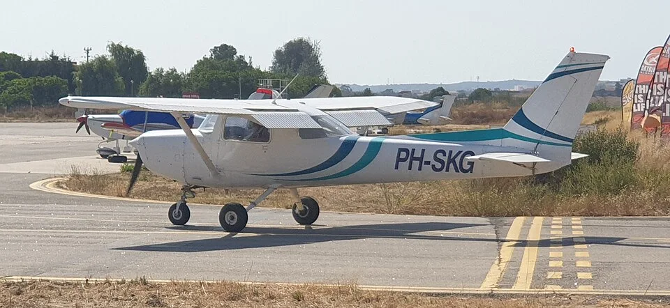
Tricycle landing gear means two main wheels and a forward nose wheel. In the fixed-gear landplane, there is no retraction cycle to change that arrangement in flight. The main gear supports the aircraft through its legs and attachments, while the nose assembly combines support, shock absorption and steering functions. The later 150M description uses tubular spring-steel main legs and an air/oil nose shock strut. Earlier gear generations require separate identification.
The change to tubular main gear in the 150L generation is a good example of a design change with a practical documentary consequence. The broad layout remains a tricycle landplane, yet the leg structure and related component questions have changed. The K-to-L comparison describes the generation; the landing-gear reference separates main-gear structure, nose components and their installation context.
Braking acts at the main wheels, while nosewheel steering is associated with the rudder-pedal system. Steering, braking and shock absorption are related ground-handling functions with different mechanisms. The brake-system article and landing-gear known issues provide the deeper distinctions. Float-equipped configurations of eligible 150 models belong to a different configuration discussion and do not inherit this wheel-based explanation unchanged.

Fuel, power and instruments inside the structure
In the stock carbureted arrangement, two wing tanks feed through a gravity-supply system to the engine. A shutoff valve, strainer, lines and venting each have a role in that supply path. Quantity indication is a separate function. The fuel-system article explains the components, while fuel capacity distinguishes total and usable quantities and the installed tank options. The wing location alone does not establish how much fuel an individual aircraft can carry.
The forward engine installation connects the powerplant with its mount, controls, fuel supply, exhaust and accessories. The familiar U.S. standard 150 uses the Continental O-200-A; the 152 uses the Lycoming O-235 family. A fixed-pitch propeller has blade pitch established by its design rather than a cockpit propeller-pitch control. The engine references and propeller references preserve exact installations, including the distinct French and conversion cases. Engine identity alone does not establish an approved propeller combination.
Electrical generation supplies the aircraft's electrical loads and charges the battery. The starter's electrical supply and the engine-driven magnetos are different parts of the architecture: magneto ignition is independent of the main bus in the stock description. The electrical article separates the earlier 150 arrangements from the later 152 system. Pitot and static pressure lines serve flight instruments, with different pressure inputs serving different indications; the pitot-static article explains those connections without equating them with the separate stall-warning system.
One family, several structural generations
The rear-window 150D, swept-tail and electric-flap 150F, and tubular-main-gear 150L show that development affected different parts at different times. The 152 inherited the recognizable later-family arrangement while changing its engine installation and other systems. A model progression is therefore not a sequence in which every component was redesigned together. Some changes are visible; others need a control, equipment or serial reference to identify them.
Aerobat and Reims identities add further branches to this picture. The Aerobat guide separates certificated Acrobatic-category variants from standard aircraft, while the Reims guide covers French designations and installations. Neither a similar silhouette nor common ancestry establishes equal maneuver approval or component interchangeability. Understanding the integrated machine gives meaning to the technical records; those records supply the exact boundaries that a family-level explanation cannot.
Explore this topic
- Cessna 150 and 152 Cabin, Cockpit and Controls - Explore Cessna 150/152 seating, doors, windows, yokes, pedals, engine controls and baggage, with the differences between important generations.