Cessna 150 and 152 Cabin, Cockpit and Controls
The Cessna 150/152 cabin places two main seats beside one another, under the wing and behind the engine. Each occupant has a side door; the instrument panel is ahead, and baggage space lies behind the seats. This compact arrangement puts the pilot, a passenger or instructor, and the principal controls in one shared space. The useful question is how the layout works for a person, rather than whether every occupant will describe it as comfortable.
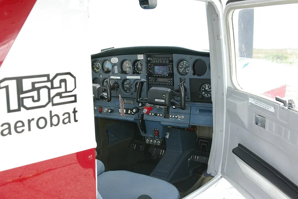

Cabin details changed during production and can change again through approved alterations. The following explanation uses the later 150M and standard 152 layout as its main reference, with earlier changes identified separately. The design article explains the surrounding airframe; this article follows access, sight lines, seating and the relationship between hands, feet and controls.
Entering a cabin built beneath the wing
The doors occupy the sides of the cabin, below the wing. Door posts and the structure around the openings are part of the fuselage, with wing and strut attachments nearby. Getting a sense of access therefore involves more than the width of a seat cushion: the door opening, the wing above it and the location of the controls all form part of the physical space. The familiar external wing strut is also distinct from the door frame.
The 150F generation brought larger doors and baggage space in the development account, and the 150G introduced curved doors associated with increased shoulder room. These are changes within the 150 line, not evidence that every 152 has a universally wider cabin than every 150. The F-to-G comparison places the door change in context. Interior upholstery, seat design and later alterations also affect the space an occupant actually encounters.
Door hardware has its own history. The 152 records distinguish a cabin-door latch change from a ventilation change within the same model-year context, with different serial boundaries. A year label does not resolve both installations. The 152 systems reference follows those narrower changes, which matter when an owner needs the correct illustration or replacement-part information.
Seats, restraints and physical reach
Two separate adjustable main seats allow the occupants' positions to be set independently. The 150M handbook describes alternative seat-adjustment designs and restraint arrangements, so a handbook illustration of an available option does not establish what is installed. Seat position influences the relationship between an occupant's eyes, the panel, the control wheel and the pedals. Cushion thickness and posture can change that relationship without changing the aircraft's nominal exterior dimensions.
Ergonomic fit is consequently a question about a person in an actual cabin. Relevant observations include reach to the pedals and engine controls, clearance around the control wheel, and the view over the panel from the seated position. These describe physical relationships, not a verdict about pilot suitability based on height alone. A published overall cabin dimension cannot capture all of them, especially when the seats or panel have been altered.
Seats and restraints are also installed equipment with a condition and a history. A seat's adjustment mechanism, its attachment and its restraint installation are different questions. The seat-rail and seat-lock reference connects seating with the applicable inspection subjects. Familiar-looking upholstery does not establish the underlying mechanism or its condition; a claim that a cabin has been refurbished does not answer those questions by itself.

Windows and the view from the seats
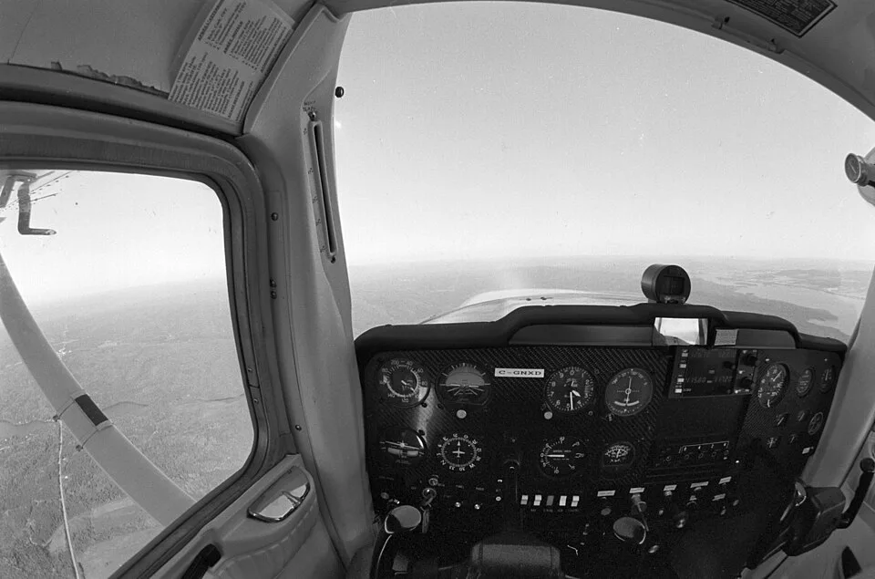
The windscreen provides the forward view, with side windows beside the occupants. The high wing, its supporting structure, door posts and the panel also occupy parts of the field of view. Describing the location of these objects is more useful than declaring visibility excellent in every direction. The view changes with eye position and aircraft attitude, and an external photograph cannot reproduce the seated perspective.
Rearward glazing marks an important 150 development step. The 150D introduced the Omni-Vision rear-window generation before the swept-tail 150F appeared. An early fastback and a later rear-window aircraft therefore differ in the cabin's rearward glazing even though both are Cessna 150s. The 150D history explains the sequence without turning a visibility-related feature into a measured field-of-view claim.
Aerobat identity adds a separate equipment context. A photograph of one Aerobat's windows, seats or restraints is not a specification for all A150, A152, FA or FRA variants. The Aerobat reference establishes the model and certification branch first. Exact installed equipment and the applicable aircraft manual are needed for the narrower cabin question; no single family photograph proves the arrangement in another aircraft.
Hands and feet connect to different systems
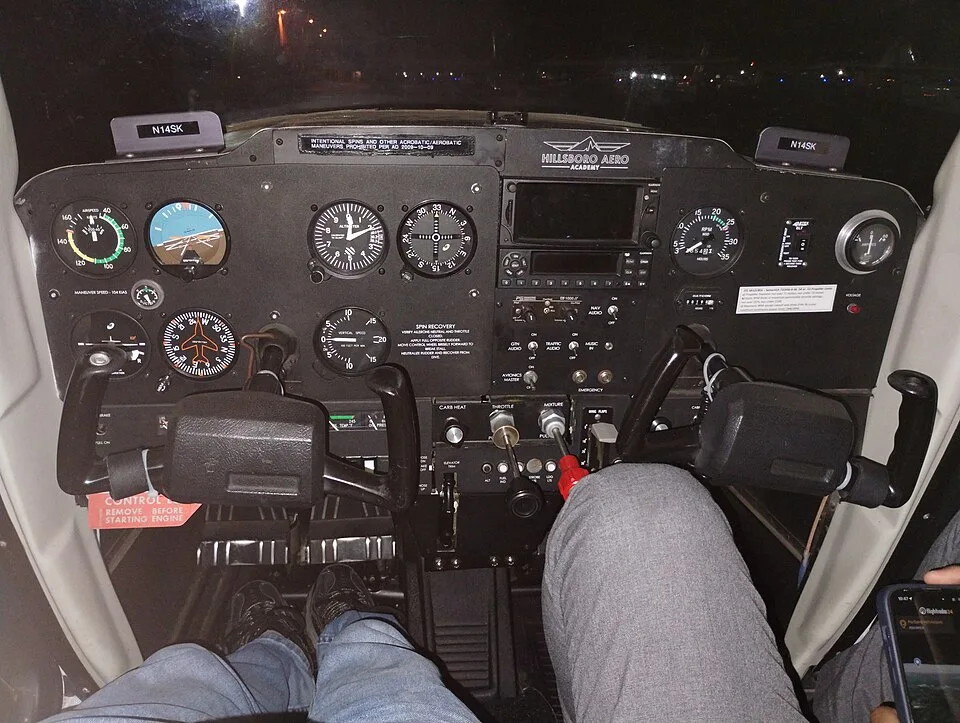
The two control wheels, often called yokes, provide the familiar hand interface with the primary flight controls. Fore-and-aft control movement relates to the elevator and pitch; wheel rotation relates to the ailerons and roll. Rudder pedals relate to yaw control and, on the ground, the nose-steering system. These are connected mechanical paths rather than independent electronic commands. The flight-control article follows the components between cockpit and surfaces.
The main-wheel brake controls are another function associated with the pedal area. Their location does not make wheel braking and aerodynamic rudder control the same action. The distinction is especially useful when reading a cockpit description alongside a landing-gear reference. The flying article explains the ground-handling relationship at a conceptual level; it does not prescribe taxi technique or brake use.
The side-by-side layout allows an instructor and student to share the panel and control environment. It does not mean that every switch, instrument or accessory is duplicated symmetrically for each seat. Panel equipment can differ between individual aircraft, and the actual arrangement matters to how occupants see and reach it. The training article explains the educational role of this shared cockpit without assigning a universal panel specification.

Engine controls have separate jobs
The throttle, mixture control and carburetor-heat control belong to different functions around the engine. The throttle changes the engine's power-setting input. The mixture control adjusts fuel-air proportion in the carbureted installation. Carburetor heat provides a heated induction-air path; it is not a cabin-heating control. A primer is a separate starting-enrichment device. Grouping these controls as engine controls should not erase those functional differences.
Their presence also distinguishes the standard fixed-pitch installation from an aircraft with a cockpit propeller-pitch control. A fixed-pitch propeller does not mean that the pilot has no engine controls; it means that propeller blade pitch is not another normal cockpit adjustment in that installation. The engine and propeller overview leads to exact equipment identities, while starting and ignition separates the starter from the magnetos.
Control location, labelling and approved use belong to the actual installation. A conversion or revised panel can change what appears familiar. This article identifies functions without giving a starting sequence, mixture setting or carburetor-heat procedure. The POH, AFM and information-manual guide explains why a general descriptive manual and the operating information applicable to a particular aircraft have different roles.
Flaps, trim, fuel and indications
Flap controls reveal a major generational difference. Early 150s through the 150E use the manual-flap architecture, while the 150F introduces electric operation. The 152 also uses electric flaps, but control details and permitted travel still require the correct model context. This is a physical cockpit change as well as a system change: the pilot's interface differs even though the controlled surfaces remain on the wings. The flap history and mechanism reference follows both aspects.
Elevator trim is separate from the main control wheel and the flap control. Through the trim system it changes the control force associated with a flight condition. Fuel shutoff and quantity indication are another pair of distinct functions: one belongs to the supply path, the other presents information about tank quantity. None of these controls can be understood simply as an extra knob on the panel; each connects to a particular system elsewhere in the airframe.
The instrument panel presents several kinds of information together. Airspeed, altitude and vertical speed have pitot-static relationships; engine indications and electrical equipment have other connections. Optional or altered instruments must be identified individually. The pitot-static explanation helps separate pressure inputs from displayed readings, and the electrical reference explains the supply architecture without assuming a uniform surviving panel.
Baggage is behind the people, but part of the loading
The baggage area is aft of the two main seats and accessed from inside the cabin in the later handbook layout. Its usefulness depends on both physical space and loading limits. An object that fits through the door and behind the seats may still make an unacceptable loading combination. Space, permitted baggage weight, total weight and center of gravity are different constraints on the same trip.
The baggage reference distinguishes documented areas and their limitations, while useful load connects occupants, fuel and baggage with the individual aircraft's empty weight. A kilogram or pound placed farther aft has a different moment from the same weight in another loading position. The current weight-and-balance records provide the aircraft-specific basis for that relationship.
Some historical 150 documentation includes an optional child's-seat installation. That is a specific equipment and loading case, not permission to treat an ordinary baggage area as another passenger seat. For the primary side-by-side training layout, the two main seats remain the relevant starting point. Seating capacity, installed restraints and approved loading must be understood together rather than inferred from unused-looking space.