Cessna 150 and 152 Electrical Systems: Generator, Alternator and Voltage
Cessna 150 electrical records distinguish an early 12-volt battery and 14-volt generator system from later alternator arrangements; the U.S. 152 reference describes a 24-volt battery and 28-volt system. Battery voltage and charging-system voltage are different descriptions. Match the model, serial and installed equipment before selecting wiring or component information.
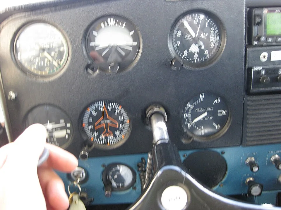

Battery voltage and charging-system voltage
The early 150 record describes a 12-volt battery with a 14-volt DC generator-regulator architecture. The later 150 record describes an alternator-regulator system and notes the 150M handbook's 60-amp alternator. The transition evidence records the 152/A152 move to 28-volt DC, with exact applicability tied to the source documents.
| Reference family | System ID | Subsystem | Factory Applicability | Architecture / Components | Operational Interface | Configuration Status | Primary Source |
|---|---|---|---|---|---|---|---|
| Cessna 150 | SYS-IGN | Ignition switch / magnetos | Stock family | Dual magnetos independent of main aircraft bus; ignition switch grounds/ungrounds magnetos. | Ignition and engine shutdown. | Exact magneto model and installation require engine and aircraft records. | [1] |
| Cessna 150 | SYS-GEN | Generator architecture | Early 150 | 12 V battery / 14 V DC generator-regulator architecture. | Electrical generation. | Exact generator amperage/equipment by year. | [2] |
| Cessna 150 | SYS-ALT150 | 150 alternator architecture | Later 150 | 12 V battery / 14 V DC alternator-regulator system; 150M handbook describes 60 A alternator. | Electrical generation. | Exact earlier alternator output/configuration by year. | [1] |
| Cessna 150 | SYS-MASTER | Master switch | Later family | Battery and alternator control; later split BAT/ALT arrangement. | Connects battery/bus and alternator field. | Era/configuration dependent. | [1] |
| Cessna 150 | SYS-PROT | Circuit protection | All | Fuses and/or circuit breakers, bus distribution and wiring. | Protects circuits. | Ratings and implementation are serial/equipment specific. | [3] |
| Cessna 150 | SYS-EXT | External power | Optional applicable aircraft | External DC receptacle/contactor arrangement where installed. | Ground starting/power. | Optional, voltage must match aircraft. | [1] |
| Cessna 152 | SYS-IGN | Ignition switch / magnetos | Stock family | Dual magnetos independent of main aircraft bus; ignition switch grounds/ungrounds magnetos. | Ignition and engine shutdown. | Exact magneto model and installation require engine and aircraft records. | [1] |
| Cessna 152 | SYS-ALT152 | 152 alternator architecture | 152/A152 | 24 V battery / 28 V DC system with 60 A alternator. | Electrical generation. | Standard stock architecture. | [4] |
| Cessna 152 | SYS-MASTER | Master switch | Later family | Battery and alternator control; later split BAT/ALT arrangement. | Connects battery/bus and alternator field. | Era/configuration dependent. | [1] |
| Cessna 152 | SYS-PROT | Circuit protection | All | Fuses and/or circuit breakers, bus distribution and wiring. | Protects circuits. | Ratings and implementation are serial/equipment specific. | [3] |
| Cessna 152 | SYS-EXT | External power | Optional applicable aircraft | External DC receptacle/contactor arrangement where installed. | Ground starting/power. | Optional, voltage must match aircraft. | [1] |
Follow the circuit's purpose
The master switch, protective devices, distribution wiring and installed loads form related parts of the electrical system. Optional external power introduces another equipment-dependent interface. Identify the relevant wiring diagram and serial effectivity before interpreting a component substitution or a repair entry.
The ignition magnetos are recorded as independent of the main aircraft bus. That distinction helps explain why the electrical load system and engine ignition should not be treated as one undifferentiated circuit. It is not a basis for improvised fault isolation or operation with a known defect.
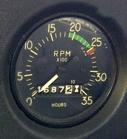

Useful records for ownership and prebuy
Ask for alteration approvals, wiring changes, equipment-list updates and the maintenance records for recurring electrical discrepancies. A changed battery location can also create a flight-control interference question; the modification's effects can extend beyond voltage or charging capacity.
The 150 service-manual reference and 152 service-manual reference explain edition and applicability boundaries. Check that the applicable manual includes its required revisions. Use the applicable controlled maintenance information for work on the aircraft.
Keep optional equipment conditional
External power and some lighting equipment are qualified by installation in the source rows. Do not convert those optional descriptions into standard-equipment claims for every model year. A practical equipment inventory should distinguish confirmed installed items, approved but absent options and items whose identity is unresolved. That distinction also makes a later wiring or load review easier to connect with the aircraft records.
The starting and ignition reference distinguishes battery-powered cranking from magnetos. The lighting guide addresses equipment-dependent circuits and the separate rheostat concern. An aft battery relocation also introduces a flight-control research question.
For historical cockpit context, the 150J model reference describes the 1969 control and switchgear changes. That model history is a publication-search lead, not serialized wiring or proof of the present panel.
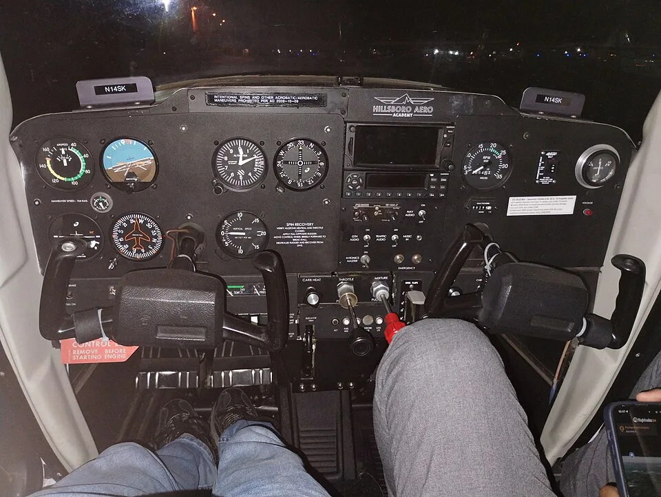

Compare generation before individual equipment
The 150F-versus-150G comparison distinguishes the F redesign from the G’s recorded alternator and cabin refinements. Keep that historical development separate from proof of an installed generator, alternator or later conversion. A charging-system enquiry should follow the aircraft and component records to the applicable wiring and maintenance material; the model-year description cannot establish the current configuration or justify using instructions for another assembly.