Cessna 150 and 152 Starting and Ignition: Battery, Starter and Magnetos
Starting and ignition are related but distinct systems in the stock Cessna 150/152 references. The starter circuit uses the aircraft electrical supply to crank the engine. The dual-magneto ignition arrangement is described as independent of the main aircraft bus, with the ignition switch controlling the magneto grounding relationship. A battery or master-switch description therefore does not fully describe ignition.
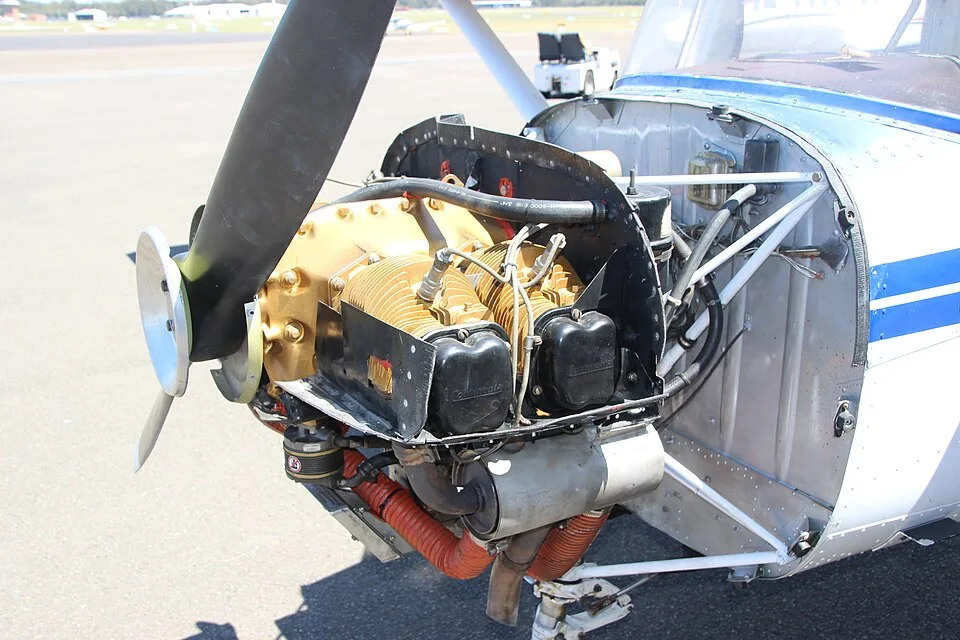

The starter circuit as an installation
The starter row identifies a battery or bus supply, start control, contactor or solenoid, and starter. It also flags the installation's voltage dependency. These are connections to identify in the correct wiring and maintenance references; they are not a wiring diagram or instructions for bridging a circuit.
| Reference family | System ID | Domain | Subsystem | Factory Applicability | Architecture / Components | Operational Interface | Configuration Status | Primary Source |
|---|---|---|---|---|---|---|---|---|
| Cessna 150 | SYS-IGN | Electrical / engine interface | Ignition switch / magnetos | Stock family | Dual magnetos independent of main aircraft bus; ignition switch grounds/ungrounds magnetos. | Ignition and engine shutdown. | Exact magneto model and installation require engine and aircraft records. | [1] |
| Cessna 150 | SYS-START | Electrical | Starter circuit | Stock family | Battery/bus, ignition/start control, starter contactor/solenoid and starter. | Engine cranking. | 12/24 V installation varies. | [2] |
| Cessna 150 | SYS-EXT | Electrical | External power | Optional applicable aircraft | External DC receptacle/contactor arrangement where installed. | Ground starting/power. | Optional, voltage must match aircraft. | [1] |
| Cessna 152 | SYS-IGN | Electrical / engine interface | Ignition switch / magnetos | Stock family | Dual magnetos independent of main aircraft bus; ignition switch grounds/ungrounds magnetos. | Ignition and engine shutdown. | Exact magneto model and installation require engine and aircraft records. | [1] |
| Cessna 152 | SYS-START | Electrical | Starter circuit | Stock family | Battery/bus, ignition/start control, starter contactor/solenoid and starter. | Engine cranking. | 12/24 V installation varies. | [2] |
| Cessna 152 | SYS-EXT | Electrical | External power | Optional applicable aircraft | External DC receptacle/contactor arrangement where installed. | Ground starting/power. | Optional, voltage must match aircraft. | [1] |
The electrical systems guide distinguishes earlier 150 and later 152 voltage architecture. Keep battery voltage, charging-system voltage and the rating of a proposed component clearly labeled. A shorthand advertisement for a “150/152 starter” does not resolve those installation details or establish applicability to a converted aircraft.
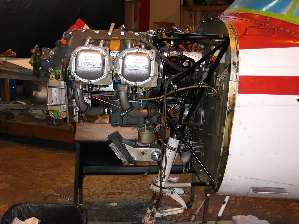

Magnetos are a separate evidence trail
The ignition architecture row describes dual magnetos rather than an ignition system powered entirely by the main bus. That distinction explains why a record concerning battery replacement does not answer questions about magneto identity or service history. Likewise, an engine overhaul entry should not be assumed to contain every subsequent accessory change.
For an engine-history review, look for the installed magneto identification and the work entries associated with those components. This page does not supply a universal replacement interval or an overhaul requirement. Such a claim would need the exact equipment, applicable instructions and relevant operating context, which the broad architecture records do not establish.
External power remains optional
The external-power entry is explicitly conditional on an applicable installation. Its inclusion in a family manual is not proof that the receptacle is fitted to a particular aircraft. Where installed, the source notes a voltage-matching requirement; the local record does not provide a ground-power connection procedure.
A buyer comparing two aircraft should record whether each has external-power equipment and how it appears in the equipment and maintenance records. Avoid treating an absent optional receptacle as an unexplained missing standard component. Conversely, an installed receptacle deserves its own configuration evidence rather than an assumption based on the model name.
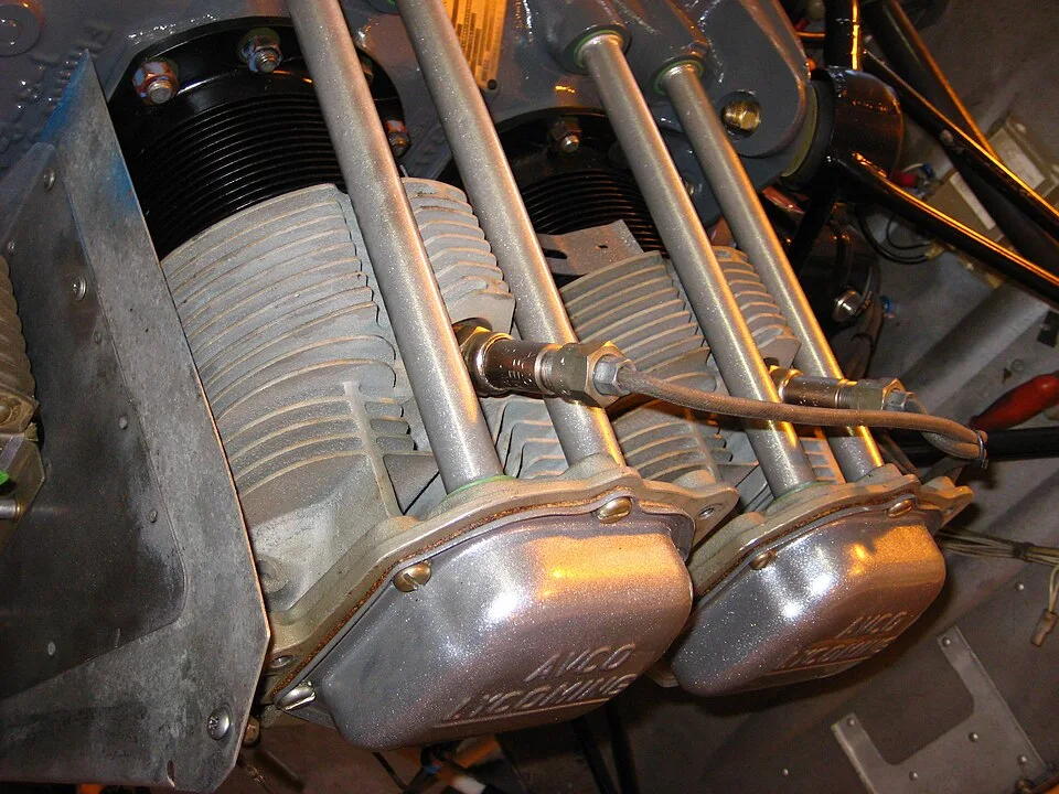

Making the records answer the right question
A useful starting-system file separates the starter assembly, electrical supply, switching equipment and ignition accessories. That makes a vague “starting problem repaired” entry easier to discuss with the inspecting mechanic: which part of the system was addressed, and which remains outside that entry? Link that review to the engine history instead of using engine hours alone as a proxy for the condition of every accessory. Identification and documentary continuity are the goals; this overview does not establish serviceability.